

Case Study
Airfield Designer
Revolutionizing Airfield Design with a Guided and Flexible Platform
Overview
RoleModel developed Airfield Designer, a sophisticated software solution for the needs of RED HORSE Groups (RHGs). The tool is capable of (1) rapid design of airfields, optimized for a choice between construction material and deployment time; (2) accurate cost and timeline estimation; and (3) efficient collaboration and communication between all stakeholders. The tool enables RHGs to support the mission-critical needs for the rapid design of airfields and runways in combat and forward environments.
RED HORSE is a construction unit of the United States Air Force. It is responsible for designing, building, repairing, and maintaining airfields, roads, facilities, and other infrastructure. This work ensures that airbases and other facilities can be established and maintained quickly. Until now, airfield design processes required intensive manual input and lacked the ability to propagate changes during the design process—resulting in months-long delays. RED HORSE needed a simpler solution for planning, designing, and building its airfields.
Overall, Airfield Designer is a powerful and versatile software solution that can help RHGs to design airfields more quickly, efficiently, and accurately. The software offers a number of significant advantages over traditional airfield design methods, and it has the potential to revolutionize the way that RHGs operate. It is flexible enough to accommodate various design requirements, adhering to UFC guidelines while allowing for real-world adjustments. It supports various design tasks, including runways, taxiways, and surfacing cut and fill calculations, and can be adapted for civilian use.
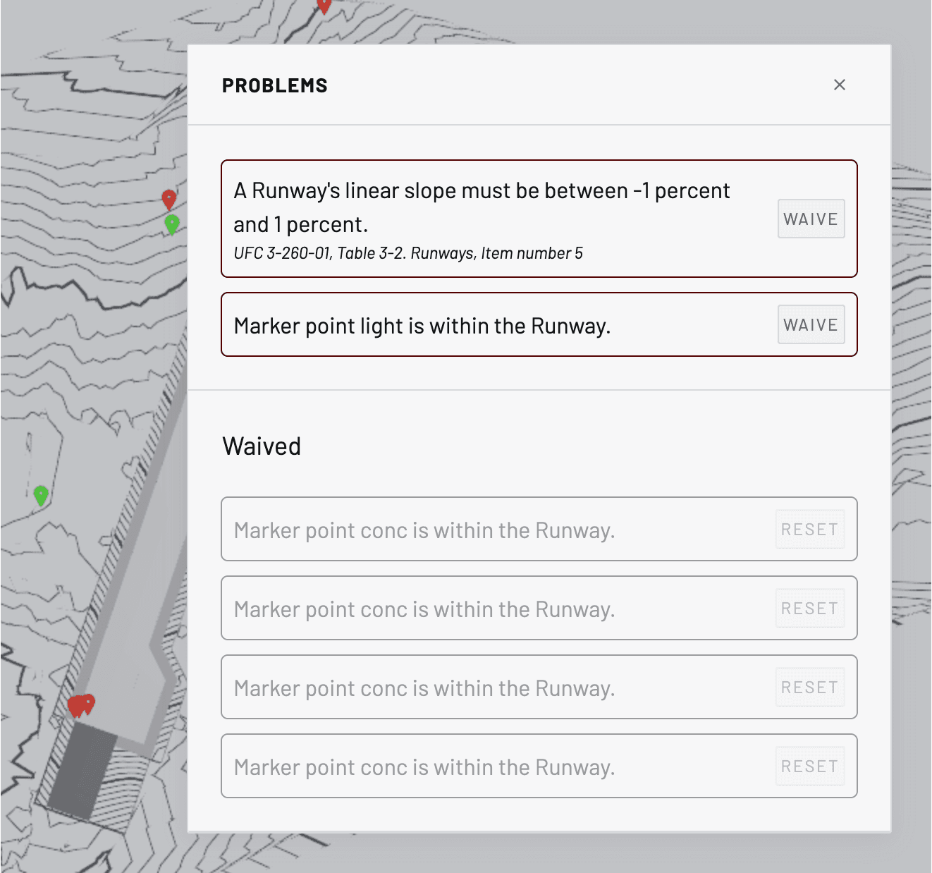
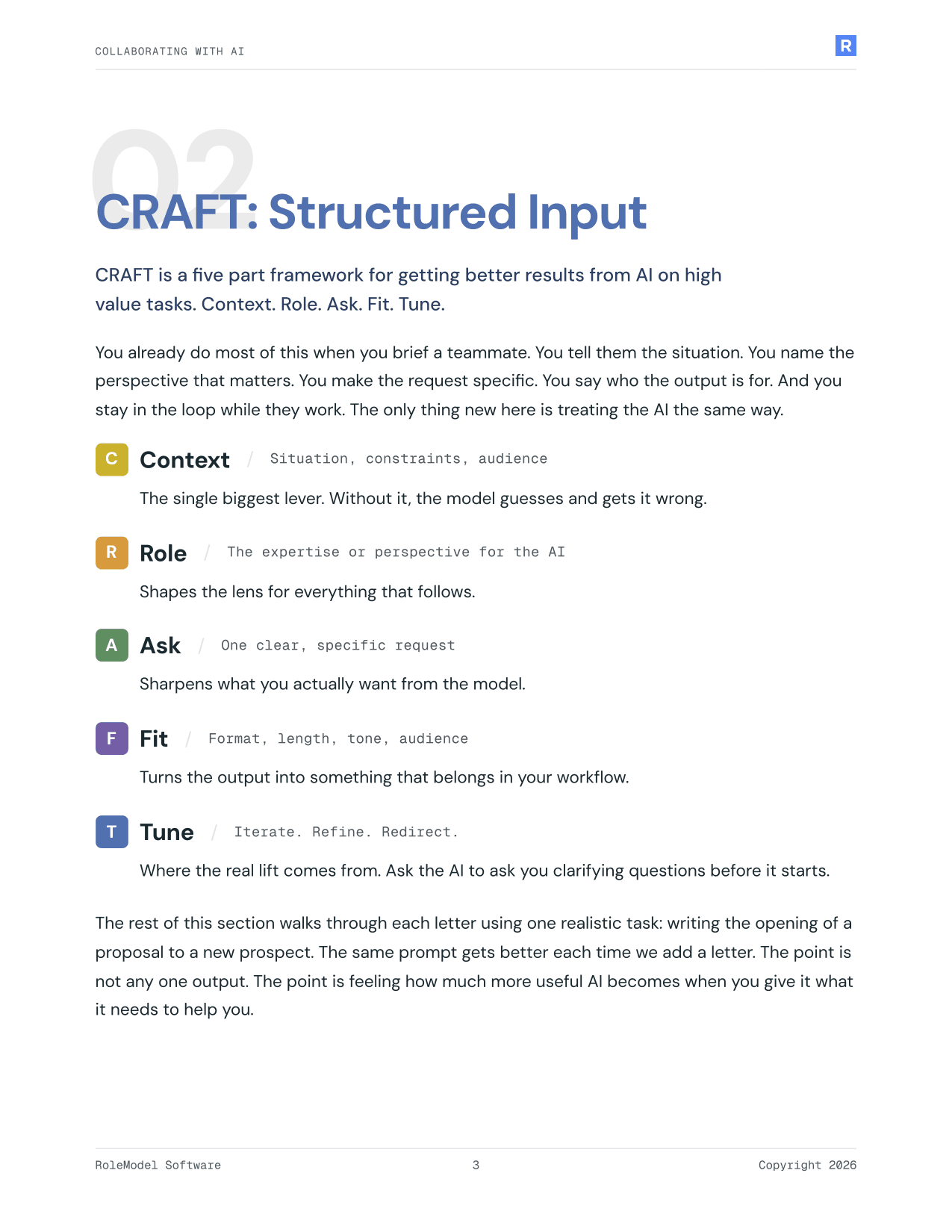
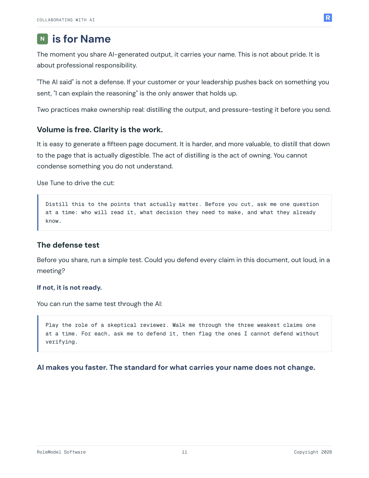
Figure 1: Airfield Designer's problems panel, listing detected obstacles and parameters with UFC guidelines, overlaid on the topographic visualization showing obstacles.
Solution Process Explained
RoleModel Software’s LightningCAD® technology underpins engineering tools for a wide variety of product verticals, but we had limited feature sets around civil engineering and terrain modeling. We have deep experience translating requirements into domain-specific Computer-Aided Design (CAD) tooling, though, and our technical point of contact within the 820 RED HORSE Squadron (RHS) communicated the scale of the problem we were attempting to solve: that in some cases, construction could be faster than the design process, and that review cycles and UFC guideline validation was eating up time. We were introduced to 820 RHS’s existing design approaches and given example survey data and construction documents to draw on, as well as the relevant UFC regulations.
Initial Solution
The first quarter of the project timeline focused on building out our ability to ingest surveyed terrain data, visualize it in the editor, place basic runways, and model the shoulders (paved and unpaved) to match basic UFC guidelines. Pavement specifications are still generated separately in the Pavement-Transportation Computer Assisted Structural Engineering (PCASE) application and input into Airfield Designer by the user, where it is used to drive grading of the terrain model and define the layer materials for the estimated Bill of Materials (BOM).
The largest value we were able to deliver in the first phase centered around runway optimization. We developed a grading engine based on our LightningCAD® framework that allowed us to rapidly automate solving runway elevation constraints to limit the fill dirt needed. For a given Easting-Northing location and runway dimensions, in a matter of seconds, Airfield Designer is able to solve for the nearest ⅛” elevation increment that does not require outside fill dirt under the runway and the graded shoulders and minimizes leftover fill. We were told that this step required time-consuming trial and error in the existing workflow, reduced to a nearly automatic operation by our tool. Alongside the Net Dirt calculation, we were also able to report on the overall quantities of construction materials required, with fuller simulation and estimation of pavement materials reserved for later stages of this Phase II project.
Design Guidelines
We distilled the geometric design requirements for USAF airfields embedded in 3-260-01 into two rulesets in our engine: one for Class A mission aircraft, and the other for larger Class B requirements. These rules were initially used to constrain design parameters, but upon review by 820 RHS we changed the implementation to permit designing outside of UFC defaults. We validate the configured model against UFC requirements and generate warnings in the Airfield Designer interface that have to be manually accepted after a waiver is obtained.

Figure 2: Exported runway terrain model breaklines authored in Airfield Designer but visualized in AutoCAD Civil 3D 2020.
Existing Toolchain Integration
Collaborating with 820 RHS, we decided on two deliverable file formats compatible with existing workflows in Autodesk AutoCAD Civil 3D® 2020: LandXML [a standard format for rich civil engineering data] for geospatial terrain models, and DXF [Autodesk’s interchange format] for generated 2D blueprints (cross-sections, pavement layouts, and paint plans). Upon testing file export of terrain models, we revised our grading engine’s implementation to produce terrain geometry that conformed to the assumptions of AutoCAD’s engine. This process also yielded a richer output, as we were also able to export the breaklines that defined the surface to AutoCAD for further editing and analysis, as well as including a number of other exportable artifacts in the file format.

Figure 3: AutoCAD rendering an exported runway cross-section plan.

Figure 4: Airfield Designer's itemized bill of materials for paving.

Figure 5: Asphalt pavement plan in Airfield Designer, demonstrating generated paving layouts for 2-paver operation, paving in echelon on a crowned runway surface.

Figure 6: A generated runway paint plan in Airfield Designer, showing adaptive paint patterns for an overrun and a turnaround attached to the runway, and options to parameterize the paint plan.
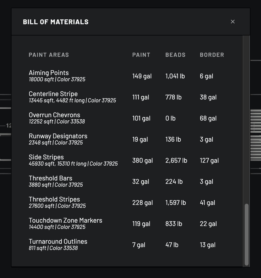
Figure 7: Itemized Bill of Materials estimated for runway paint and elements and areas.

Figure 8: Visualizing a helipad's imaginary surface (for single-direction operation), and intersecting the terrain around the helipad.

SHARE CASE STUDY


